The blog of EagleSoft Ltd!
At EagleSoft Labs, I post about the development of my various retro homebrew and video game mods, Indie video game projects, software, and electronics. I also review software, and post about other geeky/nerdy stuff.
During 2020, I released an update for my DreamPi NOOBS-compatible image (v1.21) for Raspberry Pi for the Sega Dreamcast, built against v1.7 DLE stock image.
A DreamPi
is a customized Linux distro and a set
of hardware created by a fellow named "Kazade" which will create a
simplified dialup network server in order to get a Sega Dreamcast back online for web surfing and online gaming. The DreamPi is a standardized Raspberry Pi setup with dialup hardware and appropriate software to suit. Online gaming is handled via resurrected, private
game servers. The stock DreamPi image is one which must be written to
the entire SD card of the Raspberry Pi, and thus doesn't easily allow a multi-boot setup with
other Linux distros on the same SD card. This DreamPi NOOBS-compatible
image is compatible with NOOBS or PINN bootloaders.
NOOBS is a simple bootloader which allows one to install
NOOBS-compatible distro images in such a way as to allow for a simple
multi-boot configuration, while PINN is an enhanced
version of NOOBS. PINN fixes some design flaws and adds new useful,
convenient features. PINN is highly recommended over NOOBS.
The DreamPi NOOBS compatible image works with both NOOBS and PINN, and allows
one to install a DreamPi distro with others in a multi-boot configuration. During 2020, the DreamPi NOOBS image was upgraded against v1.7 DLE, a few new online games were added to the supported games list within the installation slideshow, and online repository support was added to allow installing DreamPi NOOBS via the internet (PINN support only).
Since my older v1.7 DLE NOOBS image (v1.21) was released, 1 new game has had their online support resurrected:
I have updated the DreamPi NOOBS-compatible image to v1.22 . This and future builds will be called DreamPiDX (Deluxe) going forward henceforth, and will have community made code patches pre-installed. These patches will further enhance DreamPi with newer features and quality-of-life improvements. This latest build adds better functionality for Dreamcast BBA (Broadband) modem support and Sega Saturn Netlink/XBAND modem online gameplay.
Sega Saturn Netlink modem review
Changelog (DreamPi DX NOOBS v1.22/v1.7 DLE):
First DreamPi NOOBSDX Image release (addons to stock DreamPi image)
Separate image flavors
"DreamPi4 DX" for newer Raspberry Pi models (RPi 4 and newer)
"DreamPi" for older Raspberry Pi models
Patch addons
DreamPi Netlink Tunneler for Netlink (Sega Saturn)
Allows for web browsing, Netlink Zone/features, dialup gameplay for applicable Sega Saturn Netlink/Sega Saturn XBand modem games
If
the DreamPi is using WiFi connection for internet and Dreamcast is
using a BBA, allows to repeat/bridge highspeed broadband connection to
the Dreamcast
Updated slides with latest game listing support (Dee Dee Planet)
You can download the latest DreamPi NOOBS compatible image (for offline install) and read the guide at this EagleSoft page. The latest version can also be installed online as usual through the Tamkis NOOBS Repo; just add the line alt_image_source=http://raw.githubusercontent.com/Tamk1s/Tamkis_NOOBS_Repo/main/os_list_v3.jsonto your recovery.cmdline file at the root of your PINN installation and connect online. The images will be located under "Games" tab.
Download support through
Tamkis NOOBS Repo
For those whom want faster internet speeds and bandwidth on their Sega Dreamcast but cannot afford the rare and expensive BBA (Broadband) adapter, you can purchase and build yourself a DIY BBA Adapter using Xrider's Conversion Kit (RetroRGB article, Dreamcast Talk thread). Just salvage a G2 bus connector from an old Dreamcast dial-up modem, purchase Xrider's kit, find an Atomiswave Communication Cartridge, and solder it all together. The Sega Sammy Atomiswave was an awesome arcade version of the Sega Dreamcast with similiar hardware, more RAM, and a Broadband modem variant built-in (the Atomiswave Communication Cartridge). If you are feeling adventurous, you could also hack up both a Dreamcast dial-up modem and the DIY BBA modem together for a combo modem to have the best of both worlds without swapping out modems. (Both the dial-up and BBA modems handle different sets of games.)
DIY BBA Kit contents
DIY Sega Dreamcast BBA Converter kit tutorial
Have
fun playing online on Sega Saturn (Netlink/XBAND) gaming, and on the Sega Dreamcast with high-speed broadband internet access
Knuckles' Clackers: Project and v0.1a demo release
Since Fall of 2019, EagleSoft Ltd has been working on a Knuckles ChaotixROM hack for the Sega 32x addon privately called Knuckles' Clackers. Other than a few minor ROM hacks and one with a custom engine based on Chaotix (Sonic 4: Cybernetic Outbreak), Knuckles' Chaotix has had very few major hacks made for it. Although disassemblies of the game's code exist (M68k, SH-2, Z80 code), they are IDA Pro databases used for reference, not fully documented, and are not a split disassembly that can be rebuilt. Some research about how this game works has had information spread out throughout the internet, and isn't well documented or had most of its information consolidated into one place.
Knuckles' Clackers aims to be one of the 1st fully-fledged Chaotix ROM hacks. During development, I am further documenting, annotating, and simplifying the old IDA disassemblies of the game's code for research. Development is currently being done using SonED2 and extended ROMulan scripts to modify game data and code.
The ROM hack features some ports of Sonic Crackers beta zones (Techno Tower, Speed Slider), new SMPS32x music, new Sega 32x sprite artwork, restored beta content, and many other features.
Summary of features:
New levels
Ports and edits of beta Techno Tower and Speed Slider Zones layouts and assets from Sonic Crackers
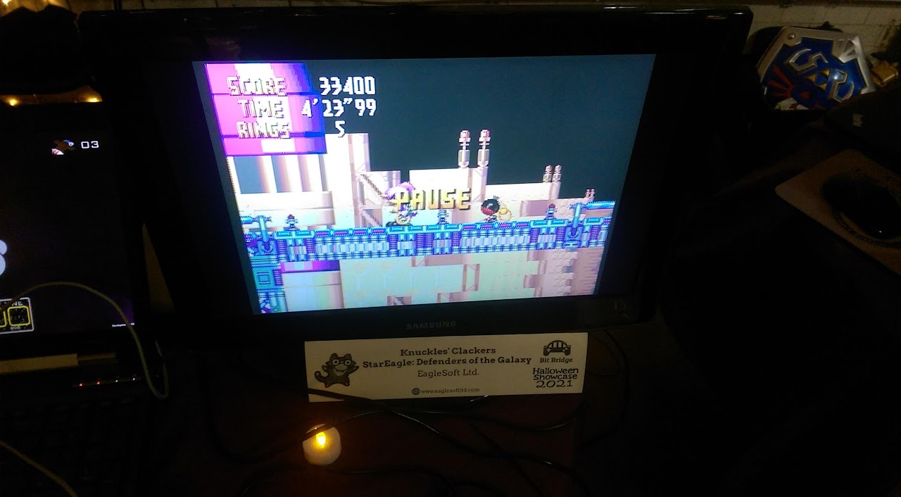
An early v0.1 demo of Knuckles' Clackers has been released for the Sega 32x, as part of 2021's BitBridge Halloween Showcase. Available here as an IPS patch.
It features acts 1-3 of Techno Tower Zone Classic, new SMPS32x music, and art edits.
Stay tuned for more Chaotix research and Knuckles Clackers' development
For those unaware of recent events within the tech industry and Google, in August 2020, Google announced that all Google Sites websites would be required to transition to their New Google Sites system by September 1st, 2021. Prior to this, in 2016 an updated Google Sites experience was deployed, and an announcement in 2017 was sent out that the previous 2016 Google Sites system (now referred to as "Classic Google Sites") would be replaced soon. In August 2020, details on the transition to New Google Sites was released. Full details below in the email screenshot.
EagleSoft Ltd. is a Google Sites website with a custom URL. This blog (EagleSoft Labs) in turn is a Blogger blog, with a subdomain of "blog" nested under the primary domain. EagleSoft Ltd. is a Google Sites website; therefore, it was required to migrate it to the New Google Sites system.
A wave of migrating crowsClassic Google Sites websites for the Fall
^deadline
Although I had a year's worth of notice about the transition deadline, in typical Engineering fashion, I procrastinated until 2 weeks before the Sept 1st 2021 deadline to do the migration 😐. The 1st week was just a single day of auto-converting the website to the New Google Sites system, followed by some more procrastination and finally tweaking and editing around the new website in the web builder interface a week before.
Apparently the New Google Sites system is too simple, too concise, too barebones, and is more tailored to say, Bloggers creating simple websites, not beautiful ones like the old EagleSoft Ltd v1.0 site was. The New Google Sites system lacks some of the great features that Classic Sites did, and is too barebones for power users such as myself. Armed with the knowledge about the New Google Sites regressions from some colleagues, I quickly plowed through a few late nights of work fixing up and reformatting the site to work in time before the deadline.
Almost a year since the v1.2 release, Thwimp,
the modification utility which allows one to view, to rip, and to
encode Nintendo THP video files from/for Mario Kart Wii, has been
updated to v1.2.0.1 today!
This is a minor update to the original v1.2 build with internal code changes and bugfixes. It contains some bugfixes for some application-breaking issues related to parsing and displaying of Single datatypes on foreign machines within the application.
Bug fixes:
Fixed various cultural issues that would cause the application to
break when processing THP videos and to display wrongly formatted data
on foreign machines
Enforced invariant culture for the bugfixes to parse and to display Single datatype values properly
Added more input validation within the THP Viewer/Ripper sections
Fixed a coding typo of handling the video end frame value as a
Single datatype instead of as a UShort in the THP Viewer/Ripper section
Enhancements:
Added a notification MsgBox on successful save of the application's log file
Updated default "Elevator Music" (song.wav) include with application to final version of Mario Kart Wii Menu SMPS32x song from my own WIP Knuckles Clackers game mod
During 2019, I released a newer version of a DreamPi NOOBS-compatible image for Raspberry Pi for the Sega Dreamcast, built against v1.7 DLE stock image. A DreamPi
is a standardized set of software (a customized Linux distro) and a set
of hardware created by a fellow named "Kazade" which will create a
simplified DC-PC server, for getting a Dreamcast back online to connect
to the Internet for browsing and online gaming, via resurrected, private
game servers. The stock DreamPi image is one which must be written to
the entire SD card, and doesn't easily allow a multi-boot setup with
other OSes on other SD card partitions. This DreamPi NOOBS-compatible
image is compatible with NOOBS or (by extension, the recommended, superior) PINN.
NOOBS is a simple bootloader, which allows one to install
NOOBS-compatible distro images in such a way as to allow a simple
multi-boot configuration, while PINN (derived from NOOBS) is a enhanced
version of NOOBS, which fixes some design flaws and adds new useful,
convenient features. PINN is recommended over NOOBS.
The DreamPi NOOBS compatible image works with NOOBS/PINN, and allows
one to install a DreamPi distro with others in a multi-boot configuration. During summer 2019 , the stock DreamPi image was upgraded to v1.7 DLE.
This has the same features as v1.7, but with the speed stability bugfix
applied and an updated DreamPi WiFi Config Wizard packaged with it.
Since my older v1.7 DLE NOOBS image (v1.2) was released, 3 new games have had their online support resurrected:
Internet Game Pack
Metropolis Street Racer
Mobile Suit Gundam: Federation vs. Zeon DX (this game looks awesome 😀)
MSG: FvZ DX
Giant robot fighting anime mechs online with the Dreamcast;
what more could I want?
You can read the
previous Dreamcast Live blog post for
information about the Changelog for v1.7 DLE.
I have updated the previous DreamPi NOOBS-compatible image (built against stock image v1.7 RPi 1-3 flavor) to v1.21. This new build features:
Updated installer slideshow
Inserted new Slide F with the 3 new games
Created a marketing.tar tarball archive with the slides_vga slideshow slides (for the online repository server support)
Both repositories allow for NOOBS online distro repository support!
Can download the NOOBS distro from online
Online auto-updating and reinstallation on PINN
Do note that this online repo support is relatively new and beta, and has only been tested with PINN. The v1.7 DLE distro currently hosted is the Raspberry Pi 1-3/Zero flavor; I only just discovered right at the time of this writing that there is a separate v1.7 DLE flavor for Raspberry Pi 4. A separate NOOBS image of the RPi 4 flavor will be built and hosted online very soon, as well as tweaks and additions made to the repository JSON files online to handle both flavors.
In order to access the distro image from the online repository, please read the instructions in the updated DreamPi NOOBS webpage. For both NOOBS and PINN, you'll need to edit your recovery.cmdline file (after first initalization of NOOBS/PINN) at the root of the SD card.
Basically summary to access the repository server:
Using either option and rebooting should allow DreamPi to show up in the "Games" tab, and be downloaded online. In order to allow auto-updating of the distro, any old versions of the DreamPi distro (installed from external media) will probably need removed and replaced from the version downloaded from the online server.
You can download the latest DreamPi NOOBS compatible image and read the guide at this EagleSoft page. The webpage has also been updated with developer information on how to serve a NOOBS-compatible image online in a repository. (NOOBS/PINN are picky on where/how the distro image files can be hosted online.) This online feature is relatively beta.
Have
fun playing online and
having DreamPi multi-boot with other OSes on NOOBS/PINN!
Thwimp,
the modification utility which allows one to view, to rip, and to
encode Nintendo THP video files from/for Mario Kart Wii, has been
updated to v1.2 today! This new update fixes, enhances, and adds the following (summary):
Bug fixes:
Fixed serious, application-breaking bug where pointing to a real
i_view32.exe IrfanView executable would cause the THP Encoder process to
fail.
Optimized THP encoding, especially when handling videos requiring dummy/control padding.
Fixed error parsing String datatype into Single datatype when in a foreign culture.
Fixed KeepInRange() function parsing bugs.
Fixed lingering file I/O from StreamReaders/Writers.
Enhancements:
Added an additional dummy entry as 0th entry in default Mario Kart Wii data fileset
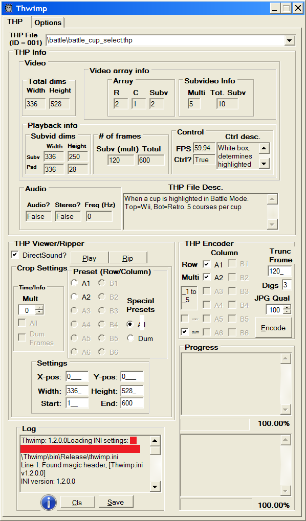
Enhanced and improved GUI.
Added new Thwimp CLI feature!
Enhanced THP Viewer/Ripper
Added new options
Full Log
Logs everything (include call to FOSS co-utilities) to the Logger
Less MsgBox
Suppress informational MsgBoxes when using the THP Encoder
Audio
Enable audio
Elevator Music
Enable elevator music (plays a song when using the THP Encoder)
Added FileSet.txt to Thwimp data fileset (displays metadata about currently loaded fileset)
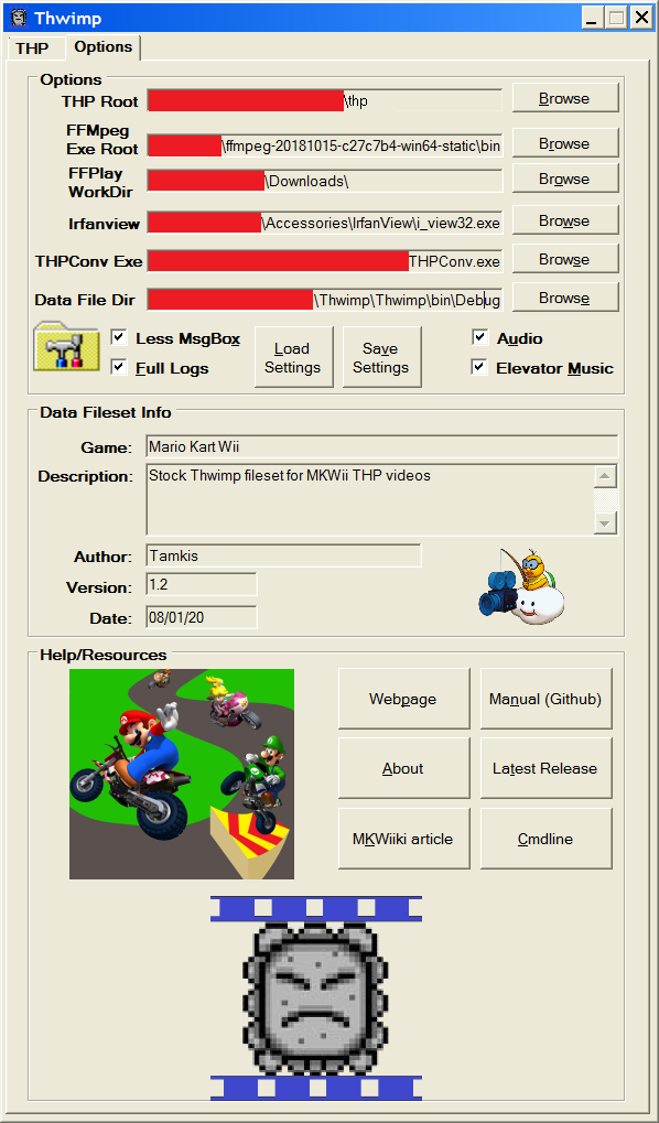
Added ability to load/save settings to/from an INI file
Added audio to application
Added progress bars/application logger
Furthermore, the user's manual (on the Github page) has been updated with updated images and information
You can view the recent GUI changes and new CLI feature in the following videos:
Download and full changelog available on the release page
First blog post for 2020 😀! Some people may be wondering what I was doing for the past 6 months, and why EagleSoft Ltd/Labs was so quiet during the hiatus. To make a long story short, I boomeranged back to a gamedev job back in early Dec. 2019 after giving up on the gamedev job search, and have been doing some remote work there lately. Then the COVID-19 pandemic/lockdown hit the nation, and I was stuck indoors for a few months at my parents' house, beating my head against the wall. The local libraries closed down (my goto quiet workplace to get work done while working remotely), and I'm surprised I kept my sanity. Trying to get my life back on track after the fiasco of late 2018-2019, I got too busy with work, though, at the same time, my lack of personal video game development/ROM hacking/blogging in my free time kept bothering and depressing me.
Now with the weather warming up, my part of the state currently in COVID Phase 2 Yellow (less restrictions), and getting caught up with work, I'm feeling the need to resume operations here at EagleSoft Ltd. for my own sanity 😀. Sometime during this summer while in Phase 2 (when I'm a little more financially stable), I'm planning on moving back out into my own apartment. Not only will this provide living independently, but I'll have my own clean, larger, organized space away from parents where I'll be able to do more nerdy stuff.
Things such as:
Fully setup my own video gaming/retro game development/entertainment mancave
Be able to use my Sony Trinitron KX2501-A RGB CRT more regularly
AV equipment
LaserDisc player
Dual VHS/DVD and (S)VCD player
(3D) Blu-Ray/HD-DVD player (PS3)
Accupix Mybud HDMI 3D glasses (3DTV)
Retro video game consoles
Games better organized
Hooked up
Readily usable
Connected to appropriate displays via AV appropriate switches
Build and design more circuits, mod/repair more consoles
A lot more stuff!
N64RGB Advanced Mod:
A quick introduction to RGB
Although this blog (EagleSoft Labs) is mostly about Indie video game development and other nerdy stuff I blog about, I occasionally post about video game console repairs, mods, or other electronic circuits I assemble. On the topic of video displays, two summers ago, I picked up a high-end, rare, special, Sony KX-2501A CRT. This CRT is known as a "component" TV, not because of YPbPr (Component) AV input, but because it comes in several pieces ("components") that need assembled.
These components consist of:
The CRT itself
Standard 2-wire (+/-) external stereo speakers for audio output
Sony VTX-1000R TV Tuner
Corresponding RM-705 remote
VK-2D/5DX (2m/5m 8 Pin DIN connector) interconnect cable between tuner and TV
Think composite equivalent of a modern-day HDMI splitter!
Handling of volume settings, RF channels
Toggle power of CRT from Tuner's power button in a master/slave setup
Being a component CRT, it's quite unique, due to the fact that the user can customize it somewhat (with their own 2-wire ghetto-blaster stereo speakers). Not only that, but it contains a Sony TrinitronCRT tube, and most importantly, it can support RGB input! Trinitron CRT tubes and RGB inputs are highly coveted items by hardcore retro gamers.
Trinitron CRT tubes are brighter than standard shadow mask CRTs (which lose 80% of their own brightness due to the shadow mask design), reduce moiré effect, and have a unique cylindrical shape. They also use utilize one electron gun to handle all 3 primary colors (Red, Green, and Blue) per "pixel" compared to 3 separate guns for each color in a conventional CRT, and additionally use vertical strips for its "pixels". (Analog video doesn't have real pixels, unlike with an HDTV.) Like with any other CRT, for retro video gaming, they also have the benefits of having no input lag compared to bad HDTVs, don't have bad scaling problems, and can properly handle any SDI signal thrown at them. Attempting to play retro video games properly on modern HDTV usually requires expensive, specialized AV equipment. Most retro video game consoles were designed and meant to be played on CRTs, not modern, hipster HDTV junk. Kids these days 👴!
Technology Connections has a great video explaining
the improvements that Trinitron CRTs have over normal CRTs
RGB, on the other hand, refers to a video signal being displayed with up to 5 separate signals:
Red
Green
Blue
Vertical Sync (VSync) and Horizontal Sync (HSync, aka RGBHV), or just Composite Sync (CSync, or RGBs)
With RGB, video is displayed by mixing the 3 separate primary color signals into one, and synchronization done by the Sync lines. As the name implies, "Sync" keeps the "pixels" aligned (synchronized) as the analog electron gun travels down the screen to display the picture, column by column, row by row. Since the video data is separated into various separate signals, and the color mixing is done on the output display end, the data is precisely read with higher quality than with other video standards.
The baseline AV interface used for most retro video game consoles was either RF (Radio Frequency) or Composite out. RF was the worst AV quality you could get; all video signals and audio stuffed into one interface cable using shielded radio signals through the cable. Needless to say, it looked bad, due to crosstalk and interference of all the analog data through the one cable. Composite video (RCA plugs with Red/White for Left/Right audio, Yellow plug for all video) on the other hand, was slightly better, since the audio signals were separated out to their own 2 plugs, and video on its own plug; however the sync information and the color information were still all stuffed into their own single cable, still causing some crosstalk, interference, and picture quality degradation.
RCA Composite Cable
RCA-styled RF modulator port from a Commodore 64
Since Digital RGB separates the video signals into up to 5 separate signals (3 color signals, upto 2 sync signals), there is far less interference, and a higher quality picture. This makes this AV standard the best quality signal for most retro game consoles. Some of the later video game consoles (such as those within the 6th video game generation, being the Sega Dreamcast, PlayStation 2, Nintendo GameCube, and Original Microsoft Xbox) had official upgraded video cables such as S-Video, Component (YPbPr), or VGA which were better or on-par with RGB, but, for the most part, Digital RGB was the best video you could get for game consoles before the 6th video game generation. Also, some of the upgraded video interfaces for the 6th video game generation could run at higher resolutions than with RGB; so sometimes it's best to use RGB for certain lower-resolution games, or the better interfaces for higher resolution games. The 6th video game generation was a special case in those regards, since the industry began transitioning to higher definition AV interfaces. (The seventh video game generation began having HDMI for certain models of the mainstream consoles, for the Sony PlayStation 3 and the Microsoft Xbox 360. The Nintendo Wii's highest official output was still just component video. The 8th generation with the Sony PlayStation 4, the Microsoft Xbox One, and the almighty NintendoWiiU finally had all 3 big industry players utilizing HDMI output.)
As for physical cable interfaces for carrying RGB data, people tend to use either SCART (a European, 21-pin AV standard carrying RGBHV/RGBs + Left/Right audio data on separate signal pins all within a single cable) or BNC on consoles, with the former being more common. SCART tended to be the baseline standard PAL European display interface for consoles back in the day. (PAL land had it posh with highest quality video stock already for retro video game consoles!) A BNC interface is usually done via up to 5 separate BNC ports: 3 ports for RGB, and up to 2 ports for HSync and VSync (or just 1 port for CSync). It's also possible to use a VGA interface (not the VGA standard over the port) to carry the RGB signals; however, this is non-standard. VGA is pretty much the same as RGB, but a 33KHz signal frequency vs. a 15KHz signal frequency respectively, and VGA using HSync & VSync, while RGB usually just uses CSync. Most NTSC consoles can natively support RGB output, by just using an appropriate console-to-SCART (or to-BNC) cable; others may need hardware modifications.
SCART Jack and
BNC connections (RGBs) on a PVM
As for displaying the RGB data onto a monitor, most NTSC American CRTs cannot do that. It usually requires a high-end PVM or BVM monitor (with either an RGB BNC interface or proprietary interface with adapters) to handle it, or modding a standard CRT to handle RGB. (Modding a standard CRT is dangerous, and should only be done if you know what you are doing, due to the high-voltage flyback transformer inside. CRTs also have a high-energy capacitor containing whole Farads of charge, and require discharging the CRT tube and other safety requirements first.)
In my case, the Sony Trinitron KX-2501ACRT is unique in that it is not a PVM or BVM monitor, yet has support for Digital RGB. This monitor utilizes a non-standard, proprietary IDC34 "Floppy" port for handling Digital RGB input, in which I've detailed my own DIY SCART/BNC+RCA to IDC34 adapter (the Sony Super Multi (X) circuit). Much more information about RGB can be found on the RetroRGB website.
IDC34 "Floppy" RGB port
SSM prototype circuit
The N64 Advanced RGB Mod:
Introduction
All of this quick retro RGB background information leads to the primary topic of this blog article; installing an Advanced N64RGB kit.
During early 2020, a friend of mine contacted me online asking how he could get an Nintendo 64 (N64) console he picked up hooked up to his modern HDMI-only display. I've heard about some HDMI N64 mods that could be done (such as UltraHDMI mod kit), but knew they were quite expensive, difficult to install, and overkill compared to say an RGB mod. (As I've mentioned earlier, most older video game consoles were designed and meant for SDI displays, not HD junk! Properly displaying these consoles on HD displays requires mods and usually expensive, specialized AV equipment, to prevent scaling issues and input lag).
Most of Nintendo's NTSC retro consoles (the Japanese Famicom, the SNES, the Nintendo 64, and the Nintendo Gamecube) used the same style of SNES AV Multi-out port. The SNES and Nintendo Gamecube can output Digital RGB simply by using an Nintendo AV Multi out-to-SCART cable; some models of the Famicom, and all models of the N64, on the other hand, require both a hardware mod in order to send an RGB signal over the port and the SCART cable.
Nintendo AV Multi-Out SCART cable
After doing some research online, I discovered a RetroRGB article about a newly released product called RAD2X. These are high-quality, proper HDMI cables for retro consoles. These are shrunken down, plug n' play, dedicated console versions of the RetroTink2x products, which properly scale the 240p resolution to 480p and send the output signal onto a modern HDMI interface. Separate RAD2X cables exist for the Sega Genesis, Sega Saturn, PlayStation AV Multi-out, and any Nintendo console that utilizes a SNES AV Multi-out plug (Japanese Famicom, SNES, N64, Gamecube), with or without an RGB mod! Rather than my friend shelling out $200+ to obtain an UltraHDMI kit and have somebody mod his N64 console simply for display on an HDTV, I suggested to him to pickup a much cheaper Nintendo RAD2X cable ($50) as an entry-level way to get both RGB and HDMI out for his N64. What's nice about the Nintendo RAD2X cable is, when using it on an N64, it can detect whether the console is outputting standard composite or RGB, and will adjust its display appropriately. (With an RGB mod, it has better color and picture quality.)
RetroRGB's RAD2X Review
(Check out 10:15 for info on its N64 RGB support)
With this information in mind, my friend asked me if I could install an N64 RGB mod into his console, so that it could display a better quality RGB picture on his RAD2X cable he would be picking up later. I hesitated at first, but agreed to do so. The mod requires doing some surface mount soldering, which I wasn't too experienced with, but did have the equipment to do so. This was also the first time I would do a serious hardware mod (and serious surface mount soldering) for somebody else, and for some extra cash on the side.
(Disclaimer: I mostly repair or mod my own consoles for fun, and I am in no way a "professional mod shop". I was rather nervous of doing the mod due to lack of SMT experience.)
(Stuff blogged here prior were just minor console repairs, including adjusting CD laser pickups potentiometers/assemblies, "re-cap" capacitor replacements, getting CD trays unstuck, replacing console chassis, and replacing a broken Nintendo Wii ODD with an older, DVD-compatible older one. Most of that SMT equipment, including an Xtronic 3020-XTS temperature-controlled soldering iron, a basic microscope, ESD tweezers and hemostat, paste-flux, ESD brushes, and an SMT practice kit I picked up back in Summer 2018 when I was designing the Sony Super Multi X dedicated circuit kits. The deluxe X version utilizes some SMT bus-switcher ICs, hence the need for upgraded tools. I haven't finalized those kit designs yet, but plan on producing them this year, due to waiting for economic stability to do a run of kits and needing to respin the design caused by some bad footprints for components in the BOM and the Bus Switcher ICs going obsolete for a similar chip with more bus I/O. This will be finished sometime after I move out into my own apartment this summer, when I'm fully rehired full-time with a wage increase, and will have a better workspace for such EET work at the apartment.)
The friend then sent by mail the N64 and basic accessories he picked up with it (power brick, official N64 controller, composite AV out cable), and I began work.
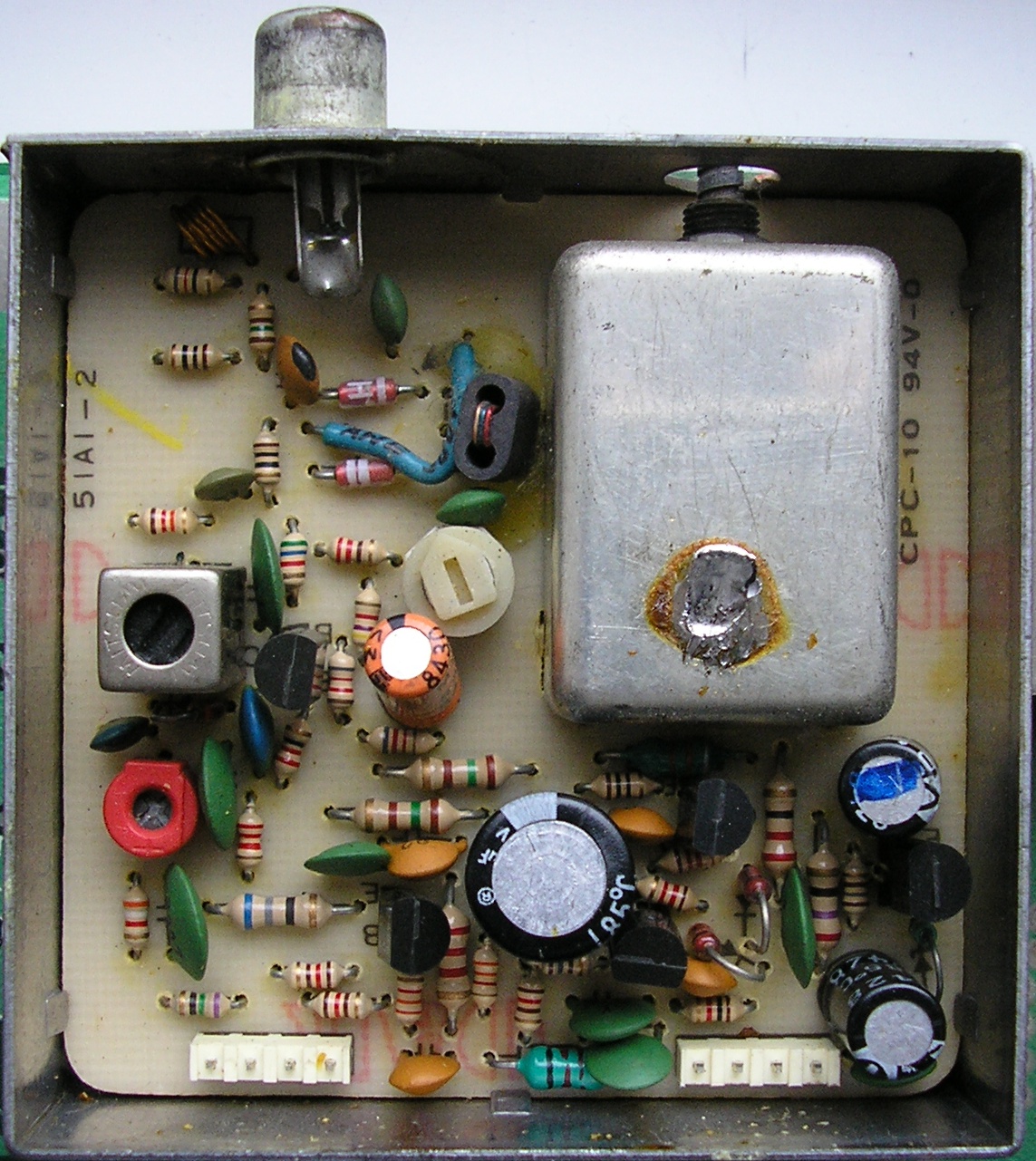
Can be determined fully by opening up console and determining DAC chip type
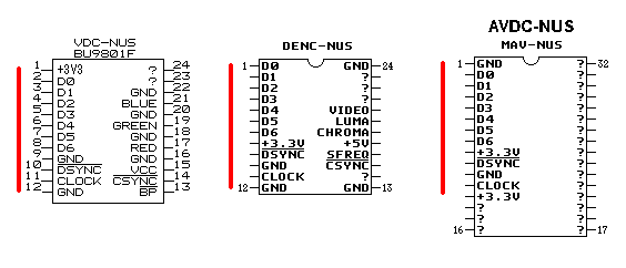
Pinouts of the various DAC chips
Upon receiving the N64, my first task was to test out the console to make sure it worked before doing any sort of modding. The console didn't come with any RAM pack for the Memory Expansion port, so I installed my old basic RAM pack. (My own N64 was upgraded with an 8MB Expansion pack years ago, and I had the old one as spare) I then proceeded to boot up the console and test all basic functionality, using a personal copy of Diddy Kong Racing and Super Smash Bros 64, and personal copies of 3 other N64 controllers, a Memory Pak, and a Rumble Pak. The supplied controller, Power Pak, and AV cable all worked, as well as all functionality for all 4 controller ports. The console seemed to be in working order!
Next step was to open the N64, and to determine fully the motherboard revision and DAC chip type inside. I fortunately already had an older model of a spare Basic RGB mod kit (from Retrofixes, pictured earlier), which I received from boss a few years ago since he had a surplus; however, this particular N64 unit was not looking promising for needing a Basic RGB kit installed, due to the serial number stickered on the bottom, and would probably need an Advanced RGB mod. As for opening up the N64, I have some high-quality 3.8mm and 4.5mm "Gamebit" security drivers in my toolbox, which I ordered a few years ago from iFixit.com (3.8mm, 4.5mm). These are high-quality bits (proper metal bit molds with a tight grip), and are deep enough to handle even the Nintendo Virtual Boy's notorious Gamebit screws, and I recommend them for anybody's toolboxes for those whom need to handle such screws on Nintendo consoles or opening game cartridges regularly.
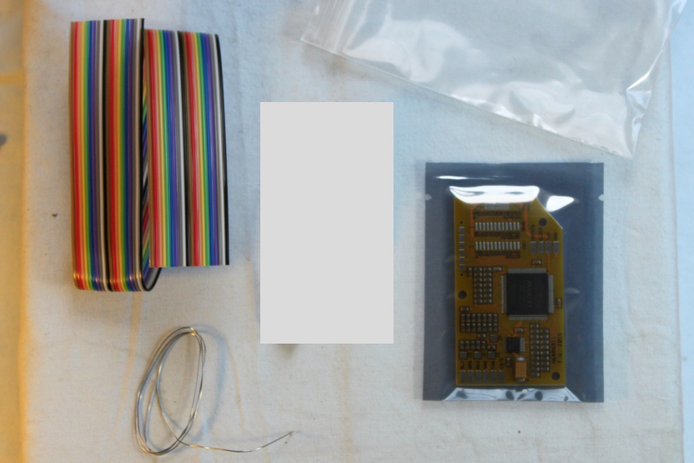
Upon opening up the consoles, it was determined that the N64 was a later model revision with a MAV-NUS DAC chip. Rats 🐀! This fact would require an Evil Tim Advanced N64RGBmod kit (see previous pictures for what is included in the kit), and is the hardest kit and DAC type to install/mod. After contacting him about the DAC chip type findings, my friend purchased and sent the over kit (with MAV-NUS chip adapter) to my residency.
The N64 Advanced RGB Mod:
Installing the mod
With the kit ordered and sent to my residency, I began work. Full instructions on how to install the kit at Tim's Advanced N64RGB installation page.Installing the Evil Tim Advanced RGB mod for a late-revision N64 utilizing a MAV-NUS DAC chip requires the following steps:
Gain access to the motherboard (remove screws)
Solder and tape down the MAV-NUS DAC chip adapter
Solder down the input ribbon cable wires from the DAC adapter to the N64RGB circuit
Strip/tin both ends of the ribbon cable wire
Tin both sets of solder pads
DAC adpater chip pads
Input pads on N64RGB Circuit
Solder down the ribbon cable wire ends appropriately
Solder down the output ribbon cable wires from the N64RGB circuit to the Nintendo AV Multi-out port
Strip/tin both ends of the ribbon cable wire
Tin both sets of solder pads/joints
N64RGB output pads
Nintendo AV Multi-output pads
Solder down the ribbon cable wire ends appropriately
Create extra ground wire, wrap it around an IC heatsink screw
Wrap up
Reassemble N64
Test it!
Step 1 was easy, and required just removing screws; a more detailed guide about that here on iFixit.com . (If you cannot even do this, you probably should stop modding 😛.)
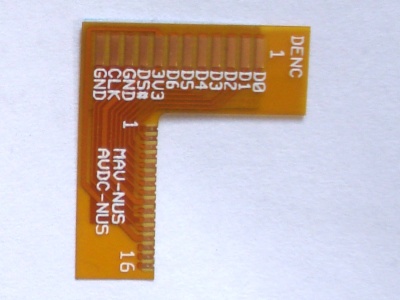
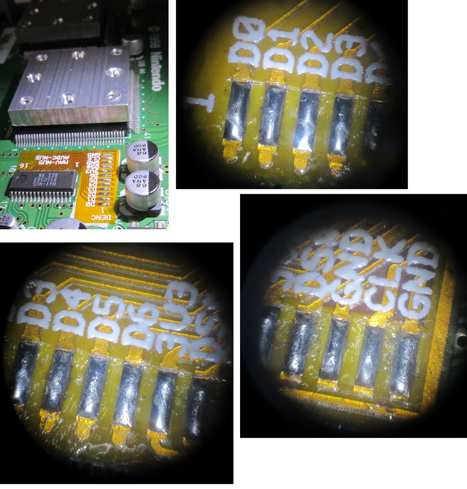
Step 2, taping down and soldering the MAV-NUS DAC chip adapter, in my own opinion, was the hardest part for me for this mod. The MAV-NUS DAC chip uses an extra-fine SMT 0.8mm pitch spacing, and is pretty much impossible to solder wires down to directly; hence the DAC chip adapter transforming the pitch from 0.8mm to 1.27mm, and breaking out the pinout to the easier DENC-NUS chip pinout. Before starting, I refreshed myself on the basics of SMT soldering (main guide, tools needed, video of basics), as well as got some blocks of spare wood to create a makeshift extended base for my microscope. (The entry-level Amscope microscope I have and its small base is meant for biology purposes, not exactly for soldering, but it works well anyways with such a makeshift, extended base).
After peeling off the adhesive tape, I aligned the adapter's input pins right up against the DAC's pins, and taped down the output end to the motherboard. Then, using the microscope, soldering iron set to a temperature of 660° F (due to surface mount work), and extra-fine strands of solder that came with the kit, I began soldering down the adapter input pins onto the DAC pins. At the time, all I had was a small jar of flux paste, which I applied to the adapter's input pins with the ESD tweezers, in order to assist with quick and solid soldering. This same jar of paste flux and the brass abrasive that came with the soldering iron I used to regularly tin the iron during the mod installation. After soldering down all the pins, I checked for continuity between the DAC adapter's corresponding input and output pins on my voltmeter, in order to check for a solid electrical connection. Throughout this mod, when the voltmeter was set to the 200Ω resistance setting, I was getting readings between 0.01 to 0.10 (so resistance values of 10mΩ to 100mΩ, with most values reading between 10mΩ to 30mΩ and being an ideal target). Amazingly, I got a solid 10-30mΩ resistance reading between all I/O pins on the chip adapter, meaning everything had continuity and was soldered down correctly, and the N64 still worked! Not too shabby for being relatively inexperienced with SMT, and even having to deal with extra-fine 0.8mm pitch joints 🆒.
Soldering down the DAC chip adapter
In Step 3, I would have to solder down the input ribbon cable wires from the DAC adapter to the N64RGB circuit. This would entail stripping and tinning both ends of the ribbon cable wire, tinning both sets of solder pads (DAC adapter chip pins, input pads on the N64RGB circuit), and finally soldering down both ends of the ribbon cable wires to both sets of pins. The ribbon cable wire supplied/required is a pesky 1.27mm pitch ribbon cable, 28 AWG gauge, stranded, and 7-core (meaning 7 individual wire strands inside). The last two times I had to deal with such pesky, stranded wire around this small size was when I worked briefly as an EET creating modbus cables from RJ45 patch cables at a company, and when designing my own Line Voltage Inducer (LVI) for a Dreamcast DreamPi. I had trouble back then stripping the wire without losing individual wire strands, and ensuring the solder connection was mechanically strong enough to hold down, and have since then hated dealing with such wire and try avoiding using such small, stranded wire as much as a I can. (Solid-core wire FTW.) Ideally, all individual strands for such stranded wire need used, since losing any strand could cause shorts, or a weaker electrical signal over the wire.
Unlike with those 2 bad experiences, this time I had my own microscope handy, so I'd be able to inspect and ensure I have all wire strands. In the installation instructions, the manual recommends stripping 3 groups of 4 wires at once from the ribbon cable, by cutting down and pulling away on such wire groups. Due to using bundled ribbon cable like this, the modder would also need to get the wires around the same length too. This group stripping tip turned out to be bad idea, since I often would accidentally lose some wire strands when stripping. I ended up ruining the 12-wire ribbon cable during the stripping part (cutted down the ribbon bundled too short when fixing mistakes for jumping the signals), and had to order an extra-long ribbon cable from eBay to redo it. Live and learn.
By the time the ribbon cable arrived, I had also ordered and received from eBay a SNES SCART cable (for testing the RGB mod when done on my Sony KX-2501A monitor via Sony Super Multi adapter), and 3 small liquid dropper bottles of awesome Kester 186 RMA flux 😀. With the new ribbon cable, this time I would separate and strip each ribbon cable wire separately (rather than in groups). I also looked up and refreshed on how to tin wire properly, by using capillary action and heat transfer.
Liquid Kester 186 RMA Flux:
The secret to quality soldering!
"Solder flows where solder's been,
so it's always best to tin, tin, tin"
This time, I had far better results and the proper length ribbon cable bundle made. All wires had all 7 wire strands soldered and tinned together (although some strands got clipped short, and I had to apply extra solder to the base to make all 7 wires still act as its own solid electrical connection), wires were twisted, and properly tinned. Getting all wires the same length wasn't perfect, but it would do. When tinning, I additionally added a tiny drop of Kester flux to the wire, to make the tinning quicker and easier for better capillary action, and used both the ESD tweezers to spread the flux across the wires, and a small cotton swab to clean up any over spill. For the tinning, I used the extra-fine solder that came with the DAC chip adapter. Unfortunately, one of the wires in the middle of the cable I botched badly with respect to getting all strands used and equal wire length with the rest of the ribbon wires, so I split the ribbon cable into 2 smaller groups, and would later solder down a single ribbon cable wire in between them to fix that at the end of the mod. Like before, I checked for continuity between both ends of the wires using a voltmeter, and still got a very small amount of resistance (10-30mΩ), so the electrical connections should be solid enough to work.
1.27mm 28 AWG
stranded ribbon cable wire (7-core)
Microscopic inspection of
input tinned ribbon cable (both ends)
Next substep would be to tin the DAC chip adapter's input pins. This was fairly straight forward, and similar to tinning the wire. (Apply a small drop of solder to solder iron tip for heat transfer, quickly heat up solder pad, and dip extra fine solder strand onto heated pad for even and smooth tinning. Like with before, apply a small drop of Kester flux onto the pads for better results, clean up over spill using cotton swab.)
A fine job on tinning
With the pads tinned, next step would be to solder the ends of the ribbon cable down to the DAC adapter input pins. This part ended up being difficult, due to the wires not being entirely straight or aligned. I had to do a 2-handed soldering operation; soldering iron in left hand in order to heat up the tinned pad and wire for soldering; and right hand to hold down and to move the wires into place, and to place them flat onto the pad, using ESD tweezers. I also unfortunately made the mistake of not trimming off the ends of the wires to make a flat end (was trying to keep wires proper, equal length), so sometimes wires would unfurl, and I would need a drop of Kester flux to help with soldering the wires down. Occasionally wire insulation did melt off due to the heat applied on the end of the wire. These facts, coupled with having to look into a microscope (within a tight mechanical space, while avoiding burning off nearby SMT capacitors) made this substep difficult. To get the wires better aligned, I applied electrical tape nearby to the ends of the wire, to apply a horizontal adhesive force and to keep them bundled closer together, and mounted the other end of the wire, to keep them taut and straight.
After fighting everything into place, I somehow miraculously still was getting a good continuity reading between everything (<100mΩ), and the wires had a solid, mechanical connection. Although this solder job would work, it could have been done better, neater, and cleaner. It was not my best soldering, but with the difficulties involved with the tiny scale, and this being my first time dealing with such small ribbon cable with major SMT soldering needed, would do.
Microscopic inspection of DAC adapter
input ribbon cable wires
Next substep would be to solder down the other end of the input ribbon cable (to the N64RGB board); same steps as before (tin pads, solder down wires into place). With the 1st end of the ribbon cable down, I had to bend out a piece of the heatsink near the Nintendo AV Multi-out port, and feed the ribbon cable through, then position the other end of the ribbon cable wire near the N64RGB input pins. To assist with that positioning, I used a magnifying glass stand, which had 2 alligator clips on each end. After removing the magnifying glass that got in the way, I used an alligator clip to position the wires nears the pads, then used the ESD tweezers for finer positioning while soldering. That N64RGB board was taped down onto the heatsink, near the chip heatsink screws. I applied electrical tape to the ribbon cable ends (better horizontal alignment), tinned the pads, applied a drop of Kester flux to the pads, and soldered down the wires. This time I also trimmed off the ends of the ribbon cable, for a flat wire easier to solder down.
The difference in soldering quality between the DAC adapter and N64RGB ends of the input ribbon cable was night and day 😀. Like usual, everything had continuity with resistance <100mΩ, and the N64 would still function. Step 3 completed!
Tinning the N64RGB input pads,
soldering down the ribbon cable wire
For step 4, I would need to solder down an output ribbon cable, doing mostly the same steps as in Step 3. (Tin the N64RGB and Nintendo AV Multi-out output pads, strip and tin ribbon cable wires, solder them down). Additionally, I would need to create an extra stripped/tinned ribbon cable wire, solder it in parallel onto the GND pin on the N64RGB output pin, and wrap that wire clockwise once onto the nearest chip heatsink screw. This extra ground wire reduces vertical lines appearing in the RGB output picture, and allows for better heat dissipation. Finally, I would need to create that single ribbon cable wire to wrap up the input ribbon cable wire I skipped from earlier.
Fortunately, the output pads on the N64RGB board were macroscopic this time, and would only require 4 ribbon cable wires, with extra-wide peeling for alignment. This task would be far easier than with the input ribbon cable. Like before, I stripped and tinned both ends of the ribbon cable, tinned the N64RGB output pads, and soldered those ends down. Additionally, I created that extra ground wire. Unfortunately, I made a very minor mistake of soldering the ribbon cable wires in reversed color and direction compared to the original instructions, but this could be remedied by making sure the correct signals still goto their correct destination, improvising the alignment and positioning of the ribbon cable wire to make sure the wires would still fit for the jump, and documenting the new color order for my friend.
Finally, I needed to solder down the other end of the output ribbon cable onto the appropriate Nintendo AV Multi-Out pins, in order to wrap up and get the port RGB enabled. Physically, this was the hardest part of the mod, due to needing to solder the wires onto the bottom side of the N64 motherboard. I had to clamp down the heatsinks (to prevent the top heatshield with the N64RGB board from falling off), and do some serious improvisation with my blocks of wood, in order to get a good, flat, stable base for soldering. Even with this improvisation, the whole setup was too high to get good optical focus for the wires under the microscope, so I had to wing it. (I could, however, lift up the microscope off the table to check out the wire soldering with better focus, but only after being done soldering. I don't have 3 hands.) Due to soldering the output ribbon cable end on the N64RGB board in the wrong direction, I had to apply a twist to 2 of the wires for better positioning for soldering to the correct Nintendo AV Multi-out pins, and I probably should have soldered down the AV output port end of the ribbon cable down first. Regardless of these minor issues, I was still able to fight everything down into place. To wrap up, I soldered down that additional, single, input ribbon cable wire I skipped; checked continuity for everything within this step (still got continuity with resistance values < 100mΩ), and screwed down that extra ground wire. Mod completed!