DreamPi: DIY Industrial LVI


In a few prior posts, I have detailed some information about getting a Sega Dreamcast back online by using a DreamPi. A DreamPi
is a standardized set of software (a customized Linux distro) and a set
of hardware created by a fellow named "Kazade" which will create a
simplified DC-PC server, for getting a Dreamcast back online to connect
to the Internet for browsing and online gaming, via resurrected, private
game servers. In a few other posts I have also detailed using and writing a customized DreamPi NOOBS-compatible image that I have created for adding the DreamPi Linux distro onto an SD card in a mulit-boot setup (via NOOBS/PINN bootloader).
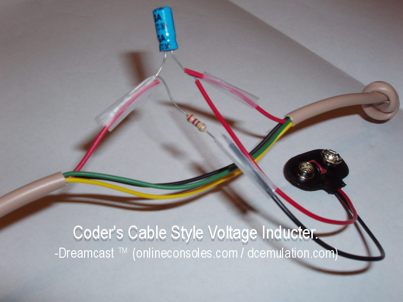
One of the main hardware components that is often required for setting up a DreamPi is a Line Voltage Inducer. Most of the dial-up 56k modems models built into most Dreamcast models require voltage on the red wire (+power line) of the RJ11 phone cable; a Line Voltage Inducer (LVI) is a simple circuit, consisting of an electrolytic capacitor, a resistor, and a 9V battery, which will apply the proper voltage to the red wire (+power line) of the RJ11 phone lack for proper operation of the Dreamcast's dial-up 56k modem.

Simple depiction of an LVI
(Not electrically functional just depiction, duh.
Pic credited to onlineconsoles.com)
Pic credited to onlineconsoles.com)
Although fellow DC scener PCWizard does sell both awesome, Linux-compatible USB RJ11 modems for DreamPis and even complete DreamPi kits at the Dreamcast Live shop, when I built my DreamPi back in January 2018, I built my own kit from scratch, by shopping for the components on eBay and making my own DIY LVI. (If you are not technical, if you would just want to have a simple
complete kit, and if you have the money, I do recommend buying from the Dreamcast Live shop in
order to support both DC Live and the scene.) Making my own DIY kit was done both to save money and for the fun/learning factor; if I remember correctly, I gathered everything for about $50, so I saved some money. (In comparison, at the time of this writing, a complete Standard DreamPi kit from the Dreamcast Live site is USD $79.99, and a Raspberry Pi 3 DreamPi Kit with WiFi support is $99.99 . My DreamPi consists of a used Raspberry Pi Model 2B kit from eBay, which uses an Ethernet connection for the internet. I saved a little more money since I already had spare components available for assembling the DIY LVI.) For the DIY LVI, I just cut open a spare RJ11 cable in half, and soldered the LVI circuit in between the halves on a spare RadioShack prototype PCB. (RIP brick and mortar RadioShack stores, you are still greatly missed in 2019 😢.)
At a previous job many years ago, I once had a summer job doing some contract EET work of wiring up some safety-related electrical equipment, which was my highest payable job to date (my High Score) of a whopping $20/hr. The main task of the job was cutting open RJ45 Ethernet cable, twisting certain pin pairs of the cable, crimping the pairs into spade terminals, and inserting the spade terminals into screw terminals of the safety devices, in order to wire up a Modbus protocol cable for the devices. Since that job, I have disliked dealing with RJ45/RJ11 cable, due to how difficult stripping, splicing, and dealing with the small gauge of this stranded wire was.
Like with the old job, one problem I found with creating that LVI (which I will now call "LVI 1.0" throughout the article) was that it was flimsy and hard to solder down. Some soldering wizards just make their own DIY LVI by soldering the circuit components directly between RJ11 wires (no PCB used, like with the simple LVI depiction above); I find doing soldering in between wires like that very difficult. Standard RJ11 wire is both very small gauge wire (either 22 or 24 AWG gauge wire, with 24 being the standard) and is usually stranded (the wire itself has various strands, must be twisted together for easy soldering, and soldered down properly as a whole for stable electrical conductivity). After some attempts, for LVI v1.0, I soldered down the RJ11 wire onto the board, and had to apply some electrical glue to prevent strain on the fragile, soldered RJ11 wire as the ends moved. Despite this, however, some of the RJ11 wires soldered down still would sometimes break off from the PCB, and I would have to redo the soldering for the affected wires. It was annoying.


A few months ago, after repairing and breaking the circuit for a 2nd time, I decided enough was enough, and to design a solderless, industrial-strength LVI. Instead of even soldering and dealing with the small, fragile, stranded gauge of wire that is RJ11 wire, I designed a better LVI (LVI v2.0). LVI 2.0 is a far more stable design, consisting of x2 4P4C RJ11 wall plates (which utilize user-friendly screws and wire terminals for each pin), a breadboard for the LVI circuitry itself; shorter, replacement plate screws and washers; and small gauge, solid-core, copper wire and 22-16 spade terminals to connect both RJ11 wall plates together and to wire up the red wire (power+ pin) to the mini breadboard with the LVI circuity. To wrap up the industrial-strength LVI, it is all enclosed in a fancy metal box, with the wall plates screwed into the top lid and bottom case (with washers), and cuts to insert the RJ11 keystones.
The whole thing cost ~<USD $15 if I remember correctly, and was pain-free to create (compared to dealing with that pesky RJ11 24 AWG gauge wire).
Parts/approx. cost:
- Metal box
- Acquired on sale from a Pat Catan's closing sale
- Pat Catan's was a local craft store, which also went RIP like RadioShack earlier this fall 😢.
- It's inventory and business has since been absorbed into Michael's another local Craft store
- Equivalent box from Michael's
- RJ11 keystone wall plates
- Steal of $0.50 each from a Pittsburgh Goodwill store 😀
- Box of 20 22-16 Spade Terminals
-


- $4 from Lowe's
- Shorter RJ11 plate screws and washers for about $2 total both from Lowe's
- Shorter screws needed because screws that came with plates were too long to fit into box
- Washers needed to clamp down wall plates to metal box halves
- LVI Circuitry
- 1μF electrolytic capacitor
- 390Ω resistor
- 9V battery terminal
- Some from either RadioShack or from part grab-bags elsewhere online
- Mini breadboard
- $4 for pack of 6 from Frentaly (eBay)
Not depicted/used yet; to be bought laterTemporarily using a small segment from my main breadboard (which currently has a prototype Sony Super Multi circuit on it)- Edit - 11/2/2020
- Viewlix CandyCab Arcade PCB Legs
- PCB legs to standoff bottom of enclosure
- Makes it possible to lay it flat (but stood off) from a surface, connect both RJ11 cables
- Habor Freight Metric drill bit set
- For drilling out M3 holes for the PCB legs


And voila, a high quality, industrial-strength LVI was created! This LVI has served to be much more sturdier than v1.0, and has been working flawlessly since. Never again do I have to deal with that pesky RJ11 wire for tweaking. Pictures below of the industrial-strength LVI masterpiece.

Entire DreamPi setup
(excuse the mess, semi-temporary living quarters)

Raspberry Pi

Sega Dreamcast


Industrial Strength LVI


LVI Circuit (on temporary breadboard)


LVI Setup


Connecting to the internet with DreamPi
and Industrial-strength LVI
(DreamPi distro output,
Quake 3 Arena,
PlanetWeb connecting to EagleSoft Ltd.)
12/16/19 Update!
Finally ordered and finished the Industrial LVI
with a dedicated mini breadboard.
Enclosure can now close shut!


11/2/2020 Update!
Drilled M3 metric holes on bottom, in order to mount PCB Legs to the bottom of the case.
This makes connection of RJ11 cables easier.


EagleSoft Ltd. and Labs has been kinda quiet lately, but behind the scenes, I have been working on a new ROM hack (a Knuckles Chaotix hack for the almighty Sega 32x), and EagleSoft Ltd's first self-published, commercial, Unity3D/C# Indie video game, titled StarEagle: Defenders of the Galaxy. More details about both games in the next 2 blog posts.
Also, that repair of getting that Sega Model Virtua Fighter arcade board is still ongoing (saving up money to gather parts needed), and also a blog post about getting that awesome NeXT Cube boot up coming soon (also saving up money for parts).
Stay tuned for those upcoming blog posts and game announcements!

0 comments:
Post a Comment
Please login with either OpenID or a Google Account, and then post your comment. Please be respectful and courteous; no spam allowed.